Install Milesight LoRaWAN Gateway UG65
This topic describes the hardware overview of Milesight LoRaWAN gateway UG65 and gives instructions on how to install, power up, and network a Milesight LoRaWAN gateway UG65.
Package contents
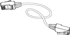
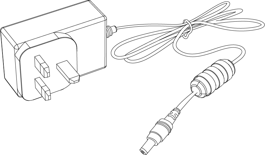
Before you begin to install the UG65 gateway, you need to check the package contents to verify that you have received the items below.
 |
 |
 |
 |
| 1 × UG65 | 1 × Ethernet Cable | 1 × DC Jack Power Adapter | 1 × Mounting Bracket |
 |
 |
 |
 |
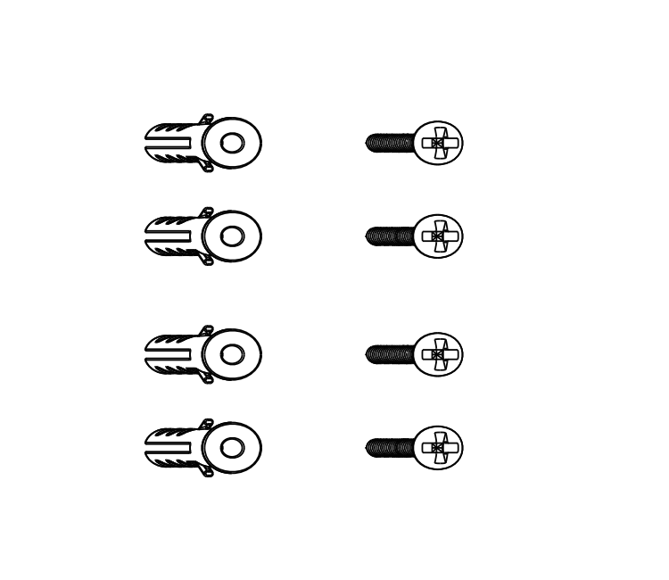
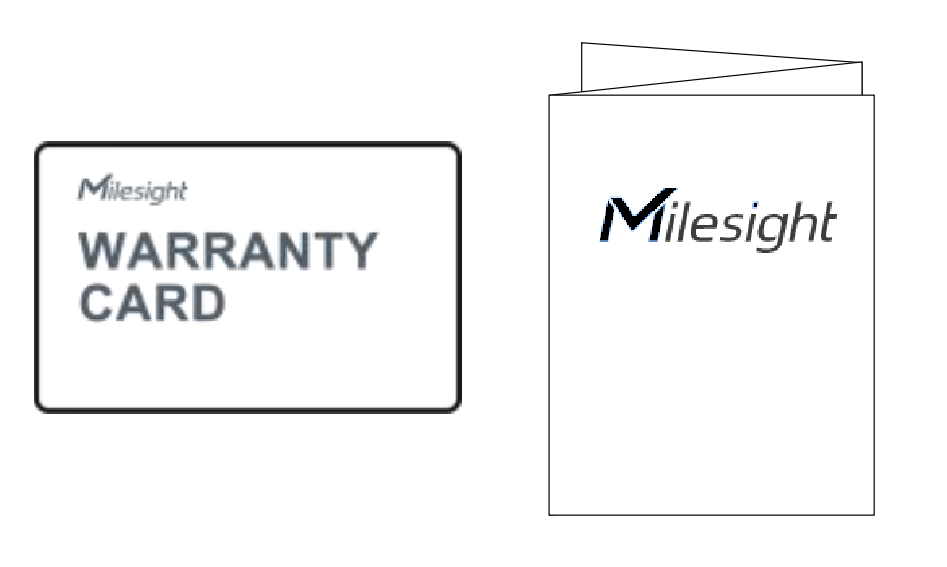
| Bracket Fixing Screws | 4 x Wall Mounting Kits | Warranty Card & Quick Start Guide |
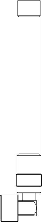
1 × LoRa Antenna (External antenna version included) |
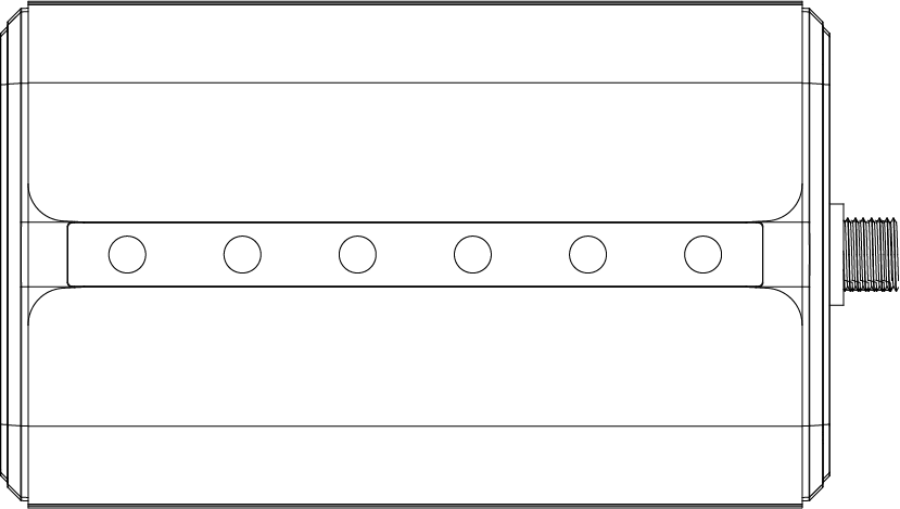
Hardware overview
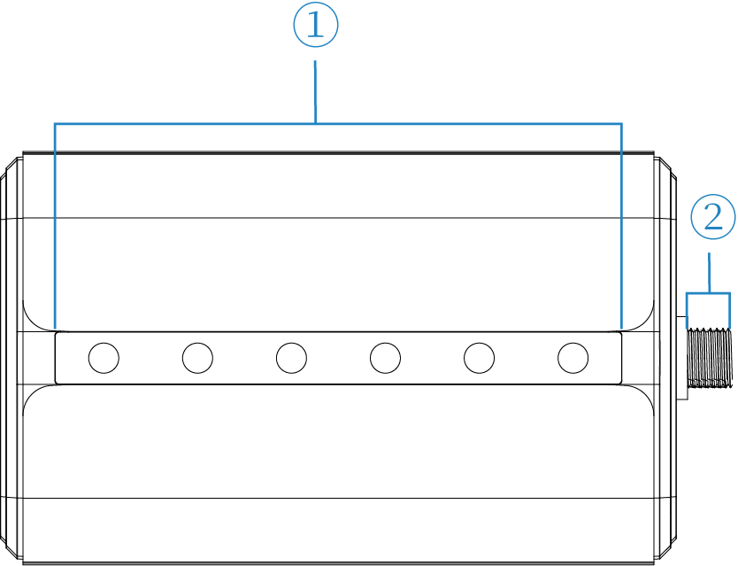
Front panel
| No. | Item |
|---|---|
|
Status LED indicators For more information, see Status Led indicators. |
|
| LoRa antenna connector (only for external antenna version) |
Status Led indicators
| LED | Indication | Status | Description |
|---|---|---|---|
| POWER | Power Status | Solid blue | The gateway is powered up. |
| Off | The gateway is powered off. | ||
| STATUS | System Status | Solid blue | The system is generally working properly. |
| Solid red | The system is experiencing a fault. | ||
| Off | The gateway is powered off. | ||
| LoRa | LoRa Status | Solid blue | Packet Forwarder mode is running normally. |
| Off |
|
||
| Wi-Fi | Wi-Fi Status | Solid blue | Wi-Fi is enabled, and users can access the gateway's configuration page by connecting to the gateway's Wi-Fi network. |
| Off |
|
||
| LTE | Cellular Status | Blue | SIM card has been registered and dialed up successfully. |
| Off |
|
||
| ETH | Ethernet Port Status | Solid blue | The gateway is connected to a valid Ethernet network by an Ethernet cable, and data is transferred on the Ethernet connection. |
| Off |
|
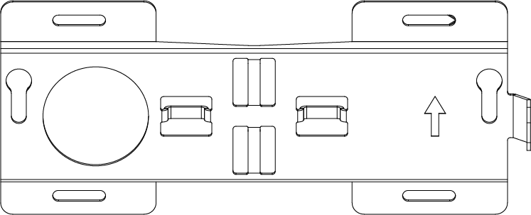
Rear panel
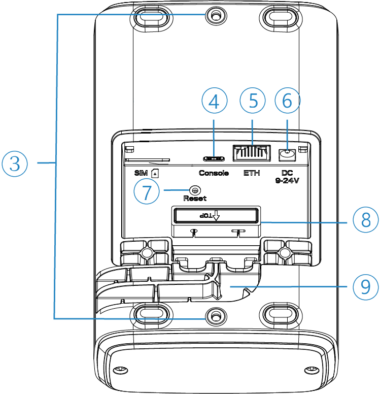
| No. | Item |
|---|---|
| |
Bracket mounting holes |
| |
Type-C port |
| |
Ethernet port (PoE) |
| |
Power connector |
| |
Reset button |
| |
Waterproof silicone |
| |
Cable groove |
Connect the Ethernet cable and power cable
| Materials required | In package contents |
|---|---|
| 1 x Ethernet cable | |
| 1 x DC power adapter | |
| Standard screwdriver |
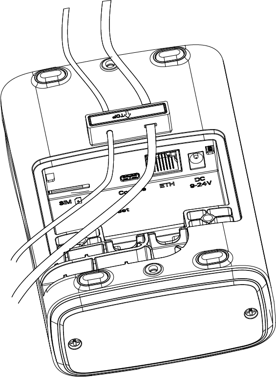
Milesight UG65 supports power supply via a DC power adapter or a PoE switch. Determine the method to power up your gateway and connect the cable(s) accordingly.
Power supply via a DC power adapter
- Unscrew the screws on the back cover of the gateway and remove the back cover.
- Pass the Ethernet cable and power cable through the waterproof silicone.
- Connect the Ethernet cable to the ETH port of the Milesight UG65 gateway.
- Connect the power cable to the power connector of the Milesight UG65 gateway.
- Place the waterproof silicone and the cables into the corresponding grooves
- Place the back cover on the gateway and tighten the screws.
 |
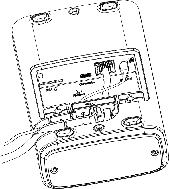 |
Power supply via a PoE switch
- Unscrew the screws on the back cover of the gateway and remove the back cover.
- Pass the Ethernet cable and through the waterproof silicone.
- Connect the Ethernet cable to the ETH port of the Milesight UG65 gateway.
- Place the waterproof silicone and the cable into the corresponding grooves
- Place the back cover on the gateway and tighten the screws.
Connect the antenna
|
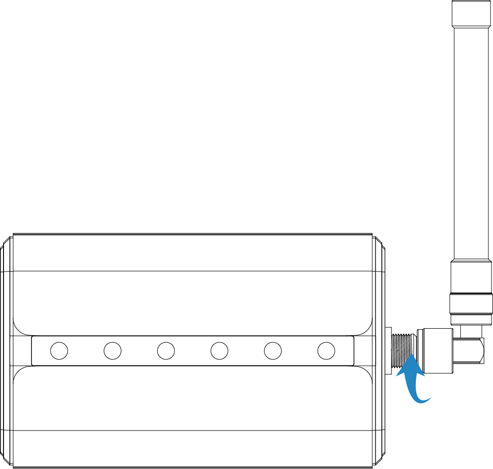 |
Mount the LoRaWAN gateway
UG65 can be mounted to a wall or a pole. Before you start, make sure your antennas have been attached and all cables have been installed.
Warning
Do not power up the gateway until installation is complete.
Mounting position
UG65 gateway supports the same floor range detection in open office buildings. It is recommended to use one gateway for one floor with the following installation notes:
- Install UG65 in the center of the connected sensors.
- Avoid being obscured by large metal objects.
- Away from high current areas and areas where current changes frequently.
- Ensure sufficient space for transmitting signals by installation in open area.
Wall mounting
Expand to see the required materials
| Materials required | In package contents |
|---|---|
| 1 x Mounting bracket | |
| 2 x Bracket fixing screws | |
| 4 x Wall plugs | |
| 4 x Wall mounting screws | |
| Marker | |
| Electric drill and a 6 mm drill bit | |
| Hammer | |
| Standard screwdriver |
 |
 |
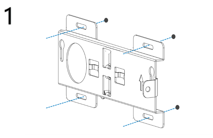
| 1. Align the mounting bracket horizontally to the desired position on the wall with the |
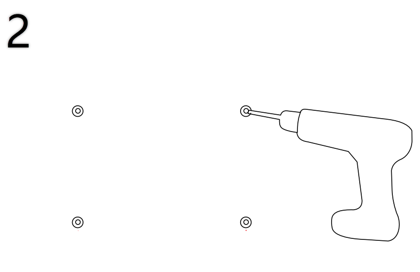
2. Drill four holes with a depth of 32 mm by using your drill with a 6 mm drill bit on the positions you marked previously on the wall. |
 |
 |
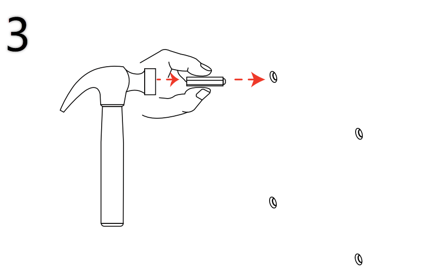
| 3. Hammer the wall plugs into the holes respectively | 4. Press the mounting bracket on the wall with the |
 |
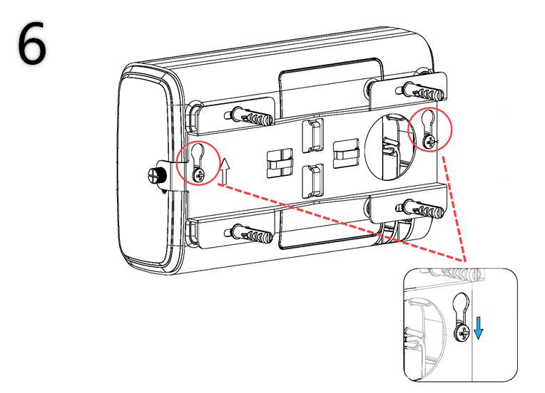 |
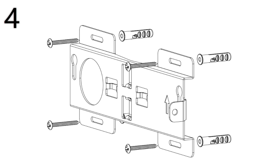
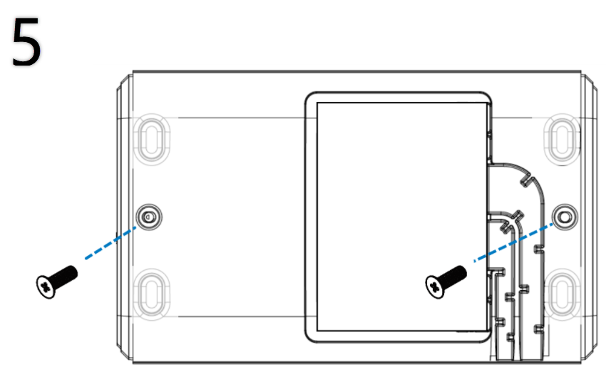
| 5. Screw the bracket fixing screws into the wall mounting holes on the rear panel of the gateway. | 6. Position the two mounting screws of the gateway into the slots on the wall mounting bracket, then slide the gateway down to sit securely in the wall mounting bracket. |
Pole mounting
Expand to see the required materials
| Materials required | In package contents |
|---|---|
| 1 x Mounting bracket | |
| 2 x Bracket fixing screws | |
| 2 x Hose clamps | |
| Standard screwdriver | |
| Screwdriver or other tools for tightening the hose clamp |
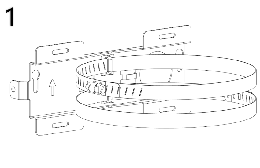 | 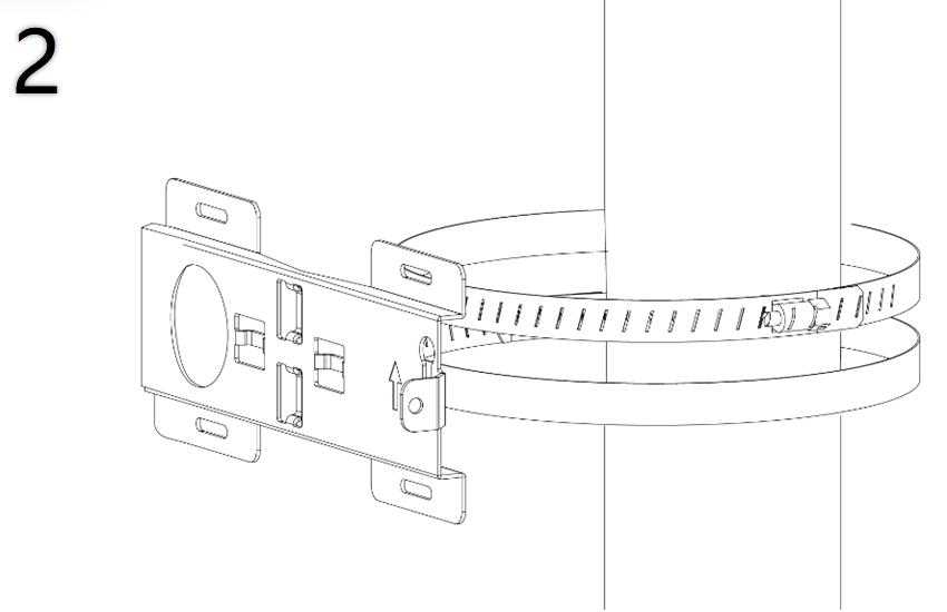 |
| 1. Loosen the hose clamps and slide the bands through the buckles on the back of the mounting bracket. | 2. Wrap the hose clamps around the pole with the |
 |  |
| 3. Screw the bracket fixing screws into the wall mounting holes on the rear panel of the gateway. | 4. Position the two mounting screws of the gateway into the slots on the mounting bracket, then slide the gateway down to sit securely in the mounting bracket. |
Power supply and network connection
Milesight UG65 gateway can be powered via a DC power adapter or a PoE switch. Choose one of the following methods to power up the gateway and connect it to the network.
DC power adapter power supply and network connection
-
Connect your gateway to the network:
Connect the Ethernet cable of the gateway to a switch/router.
-
Power on your gateway:
Plug the DC power adapter of the gateway into a standard electrical wall socket.
When the Power and ETH LED indicators on the gateway turn solid blue, the gateway is powered on and connected to the network.
PoE switch power supply and network connection
-
Connect your gateway to the network:
Connect the Ethernet cable of the gateway to a PoE switch.
-
Power on your gateway:
Gateways connected to a PoE switch are automatically powered on via the Ethernet cable.
When the Power and ETH LED indicators on the gateway turn solid blue, the gateway is powered on and connected to the network.
What to do next
After installation, you can register the gateway to Yeastar Workplace.
Created: December 16, 2021