Set up Disaster Recovery (Yeastar SD-WAN)
If you have connected two Yeastar P-Series Software Editions in different locations using Yeastar SD-WAN, you can set up disaster recovery on the two PBXs to ensure the continuous availability of essential telephony services in the event of a disaster.
Requirements
Both servers in a disaster recovery pair must meet the following requirements.
| Item | Requirement |
|---|---|
| Product Model | Yeastar P-Series Software Edition |
| Plan | Ultimate Plan |
| Version | Same firmware version and must be 83.12.0.57 or later. |
| Network |
|
| External Storage | Identical storage device settings and mounting points. |
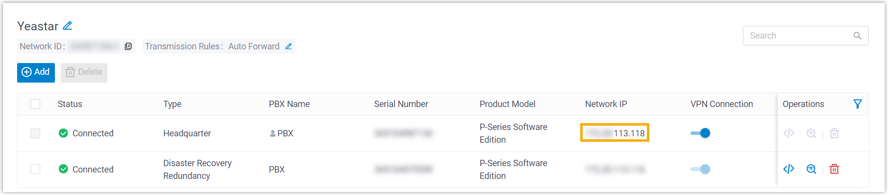
Step 1. Connect two Yeastar P-Series Software Editions using Yeastar SD-WAN
Connect two Yeastar P-Series Software Editions to the same virtual network using Yeastar SD-WAN.For more information, see Set up SD-WAN Network on Working Server and Join SD-WAN Network on Redundancy Server.
Step 2. Set up disaster recovery on the two Yeastar P-Series Software Editions
- Log in to PBX web portal, go to .
- Enable disaster recovery and set the remote networking method.
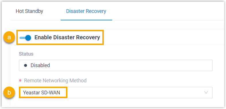
- On the top of the page, turn on the Enable Disaster Recovery switch.
- In the Remote Networking Method drop-down list, select Yeastar SD-WAN.
- Complete the following settings for the disaster recovery pair.
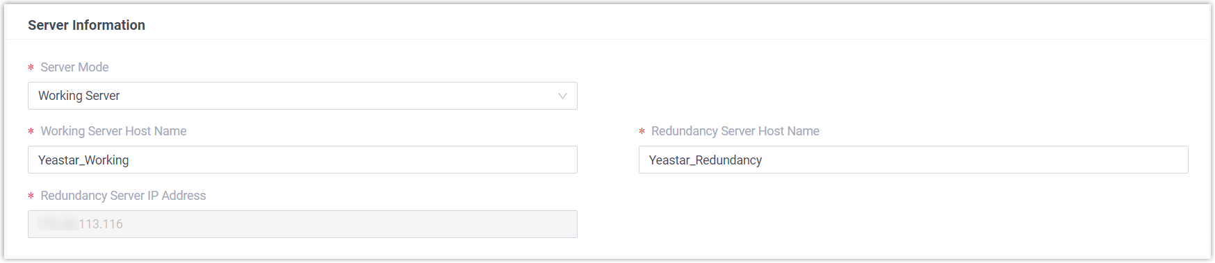
- Working Server
-
Setting Description Server Mode Select Working Server. Note: If you have set up Hot Standby, only the Primary Server can act as Working Server.Working Server Host Name Enter a name to help you identify the Working Server when receiving event notifications.
Note: The Working Server Host Name set in the Working Server and Redundancy Server should be the same to avoid confusion in event notifications.Redundancy Server Host Name Enter a name to help you identify the Redundancy Server when receiving event notifications.
Note: The Redundancy Server Host Name set in the Working Server and Redundancy Server should be the same to avoid confusion in event notifications.Redundancy Server IP Address Automatically synchronize the network IP assigned to the Redundancy Server within the SD-WAN network. 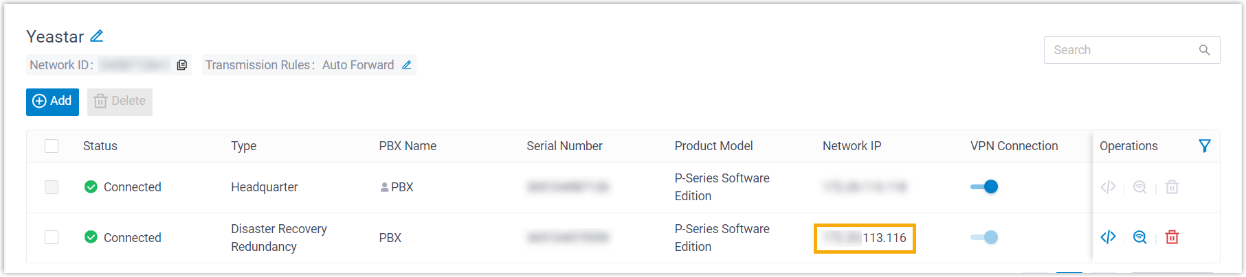
- Redundancy Server
-
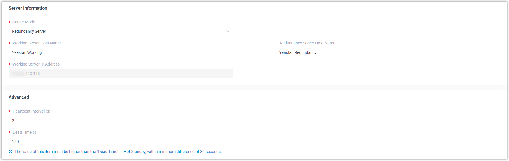
Setting Description Server Information Server Mode Select Redundancy Server. Working Server Host Name Enter a name to help you identify the Working Server when receiving event notifications.
Note: The Working Server Host Name set in the Working Server and Redundancy Server should be the same to avoid confusion in event notifications.Redundancy Server Host Name Enter a name to help you identify the Redundancy Server when receiving event notifications.
Note: The Redundancy Server Host Name set in the Working Server and Redundancy Server should be the same to avoid confusion in event notifications.Working Server IP Address Automatically synchronize the network IP assigned to the Working Server within the SD-WAN network.
Advanced Heartbeat Interval (s) Define the frequency to send heartbeat packets. The default value is 2 seconds, which means that the Redundancy Server sends packets every 2 seconds to detect whether the Working Server is alive or not.
Dead Time (s) Define the maximum time interval before the Working Server responds to the Redundancy Server. The default value is 150 seconds. If the Redundancy Server receives no response after timeout, it will take over the telephony services automatically.Note: If you have set up Hot Standby, the value set here MUST be greater than the Dead Time in Hot Standby, with a minimum difference of 30 seconds.
- Click Save.
The system prompts that you need to reboot the PBXs to make disaster recovery take effect.
Result
- On Working Server, the status is displayed as
Working, indicating that the server is running to
provide all PBX functions.
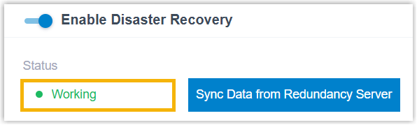 Note: The Sync Data from the Redundancy Server button that appears next to the Status field can be used to synchronize data (CDR and recordings) from the Redundancy Server, so as to eliminate the data differential after the Working Server takes over service, or when both servers ran independently due to a temporary network interruption.
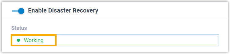
Upon successfully synchronized, the relevant contacts will receive a Working Server Manual Data Synchronization Completed event notification.
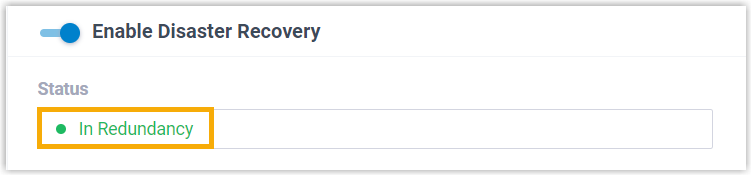
- On Redundancy Server, the status is displayed as In
Redundancy, indicating that the server is in redundancy
status. The Redundancy Server will now replicate data from the Working
Server.
What to do next
Read Server Redundancy on SIP Trunks and WebRTC Trunks and Server Redundancy on SIP Devices and Linkus UC Clients to learn how server redundancy can be implemented on trunks and extension endpoints.