S300 Overview
Front Panel (1*EX30 + 2*EX08)
Note: Yeastar S300 V4.0 only
supports 2 expansion boards. You can install EX08 board or EX30 board according to
your needs.
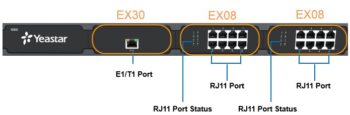
| Port | Description | ||
|---|---|---|---|
| E1/T1 | Connect the E1/T1 line. | ||
| 1-8 Port (RJ11 port) |
Note: The sequence number of the ports corresponds to that of
the Indicator lights in the front panel. (I.e. the LED
lights in the front indicate the connection status of the
corresponding ports at the back panel.)
|
||
| LED | Indication | Status | Description |
| 1-8 (RJ11 port status) |
FXS | Green: static | The analog phone is idle. |
| Green: blinking | The analog phone is busy. | ||
| GSM/3G/4G | Red: static | The GSM/3G/4G Trunk is idle. | |
| Red: blinking slowly | No SIM card. | ||
| Red: blinking rapidly | The GSM/3G/4G trunk is in use. | ||
| BRI | Orange: blinking | The BRI line is disconnected. | |
| Orange: static | The BRI line is connected or in use. | ||
| FXO | Red: static | The PSTN line is idle. | |
| Red: blinking slowly | No PSTN line is connected to the FXO port. | ||
| Red: blinking rapidly | The PSTN line is busy. | ||
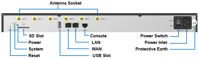
Rear Panel
| LED | Indication | Status | Description |
|---|---|---|---|
| POWER | Power status | On | The power is switched on. |
| Off | The power is switched off. | ||
| SYSTEM | System status | Blinking | The system is running properly. |
| Static/Off | The system goes wrong. | ||
| Port | Description | ||
| WAN/LAN |
Yeastar S300 provides two 10/100/1000Mbps adaptive RJ45 Ethernet ports, and supports 3 Ethernet modes. The default mode is “Single”.
|
||
| SD | Insert SD card to store auto recording files. | ||
| Reset button | Press and hold for 10 seconds to restore the factory defaults. | ||
| USB | Insert USB device to store auto recording files. | ||
| Console | Connect RS232 line to debug the system. | ||
| Power Switch | Press this button to switch on/off the device. | ||
| Power Inlet | Connect the supplied power supply to the port. | ||
| Protective Earth | Connect to the ground to reduce the risk of electrocution to the user or protect the PBX from the bad effects of external noise in the case of a lightning strike. | ||
| Antenna Socket | Rotate the antenna into the Antenna Socket. | ||