Yeastar P520 Overview

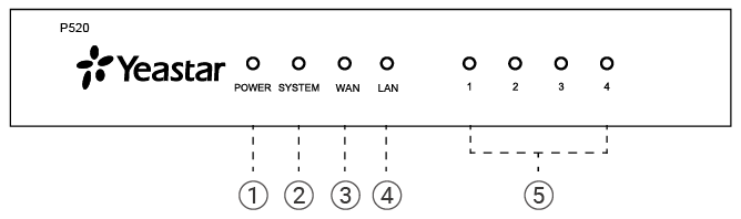
Front panel

No. Indicator Description
① Power Indicator Indicate the power status.
② System Indicator Indicate the system status.
  • Blinking: The system is working properly.
  • Static/Off: The system goes wrong.
③ WAN Indicator Indicate the WAN connection status.
④ LAN Indicator Indicate the LAN connection status.
⑤ 1-4 LED (RJ11 port status) Indicate the ports' status.
  • FXS:
    • Green: static: The analog phone or fax machine is idle.
    • Green: blinking: The analog phone or fax machine is busy.
  • GSM/3G/4G LTE:
    • Red: static: The GSM/3G/4G LTE trunk is idle.
    • Red: blinking slowly: No SIM card.
    • Red: blinking rapidly: The GSM/3G/4G LTE trunk is in use.
  • BRI:
    • Orange: static: The BRI line is connected or in use.
    • Orange: blinking: The BRI line is disconnected.
  • FXO:
    • Red: static: The PSTN line is idle.
    • Red: blinking slowly: No PSTN line is connected to the FXO port.
    • Red: blinking rapidly: The PSTN line is busy.

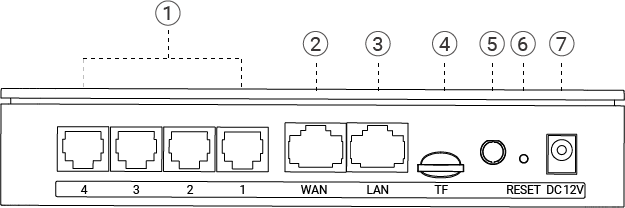
Rear panel

NO. Button or Interface Description
① 1-4 port (RJ11 ports)
  • FXS port (green light): For the connection of analog phones or fax machines.
  • BRI port (orange light): For the connection of ISDN BRI lines.
  • FXO port (red light): For the connection of PSTN lines or FXS ports of traditional PBX.
② WAN Port For connection to Wide Area Network (WAN).
③ LAN Port For connection to Local Area Network (LAN).
④ TF Card Slot Insert a TF card into the TF Card Slot.
⑤ Antenna Socket Rotate the antenna into the Antenna Socket.
⑥ Reset Button Press the button and hold for 10 seconds to restore to factory defaults.
⑦ Power Interface: DC 12V Connect the supplied power supply to the port.