Hardware Overview
Descriptions of LED indicators and ports on Yeastar K2 IPPBX.
A. Front Panel
Front panel of Yeastar K2 IPPBX and Yeastar K2 Lite IPPBX.
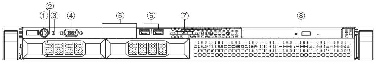
| Item | Indicator,button or connector | Description |
|---|---|---|
| 1 | Power-on indicator, power button | Enables you to know the power status of the system. The power-on indicator glows when the system power is on. |
| 2 | NMI button |
Enables you to troubleshoot software and device driver errors when running certain operating systems. This button can be pressed by using the end of a paper clip. Use this button only if directed to do so by qualified support personnel or by the operating system's documentation. |
| 3 | System identification button | Enables you to locate a particular system within a rack. The
identification buttons are on the front and back panels. When
one of these buttons is pressed, the LCD panel on the front and
the system status indicator on the back flash until one of the
buttons is pressed again. Press the button to turn the system ID on and off. If the system stops responding during POST, press and hold the system ID button for more than five seconds to enter BIOS progress mode. To reset iDRAC (if not disabled in F2 iDRAC setup) press and hold the button for more than 15 seconds. |
| 4 | Video connector | Enables you to connect a display to the system. |
| 5 | Diagnostic indicators | The diagnostic indicator glows to display error status. For more information, see Diagnostic Indicators. |
| 6 | USB connector | Enables you to connect USB devices to the system. The port is USB 2.0-compliant. |
| 7 | Information tag | Contains system information such as service tag, NIC, MAC address for your reference. The information tag is a slide-out label panel. |
| 8 | Optical drive | Enables you to install an optional slim SATA DVD-ROM drive. |
Diagnostic Indicators
The diagnostic indicators on the front panel display the system status during startup.
The system equipped with an LCD panel does not provide diagnostic indicator.
No diagnostic indicators are lit when the system is turned off. To start the system, plug it into a working power source and press the power button.
| Icon | Description | Condition |
|---|---|---|
 |
Health indicator | The indicator turns solid blue if the system is in good health. |
The indicator flashes amber:
|
||
| Hard drive indicator | The indicator flashes amber if there is a hard drive error. | |
| Electrical indicator | The indicator flashes amber if the system experiences an electrical error (for example, voltage out of range, or a failed power supply unit (PSU) or voltage regulator). | |
| Temperature indicator | The indicator flashes amber if the system experiences a thermal error (for example, the ambient temperature is out of range or fan failure). | |
 |
Memory indicator | The indicator flashes amber if a memory error occurs. |
 |
PCle indicator | The indicator flashes amber if the PCle is error. |
B. Back Panel
Back panel of Yeastar K2 IPPBX and Yeastar K2 Lite IPPBX.
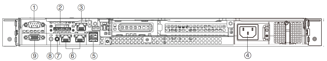
| Item | Indicator, button, or connector | Description |
|---|---|---|
| 1 | Serial connector | Enables you to connect a serial device to the system. |
| 2 | vFlash card slot (optional) | Enables you to connect the vFlash card. |
| 3 | iDRAC port | Enables you to install a dedicated management port card. |
| 4 | Power supply unit | Enables you to install up to two 350 W AC PSU. |
| 5 | USB connectors | Enable you to connect USB devices to the system. The port is USB 3.0-compliant. |
| 6 | Ethernet connectors | Enable you to connect integrated 10/100/1000 Mbps NIC connector. |
| 7 | System identification button | Enables you to locate a particular
system within a rack. The identification buttons are on the front
and back panels. When one of these buttons is pressed, the LCD panel
on the front and the system status indicator on the back flash until
one of the buttons is pressed again. Press the button to turn the system ID on or off. If the system stops responding during POST, press and hold the system ID button for more than five seconds to enter BIOS progress mode. To reset the iDRAC (if not disabled in F2 iDRAC setup) press and hold the button for more than 15 seconds. |
| 8 | System identification connector | Connects the optional system status indicator assembly through the optional cable management arm. |
| 9 | Video connector | Enables you to connect a VGA display to the system. |