Install Yeastar K2 IPPBX(Rack Mount)
Install the Yeastar K2 IPPBX in a rack and connect the cables to the PBX.
Yeastar K2 IPPBX support four static rail solutions:
-
Tool-less, round- or square-hole (four-post) in step 2
-
Tooled flush-mount rails (two-post) in steps 3 and 4
-
Tooled center-mount rails (two-post) in step 4
-
Tooled flush-mount rails (four-post) in steps 5 and 6
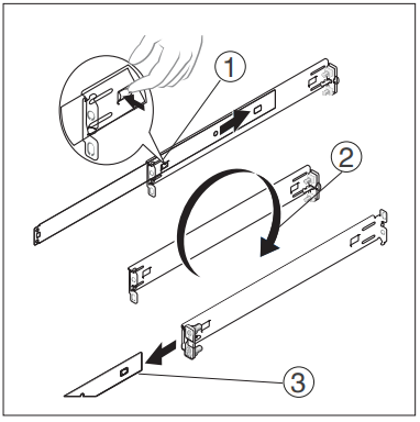
Step 1. Identify the Static Rail Kit Contents
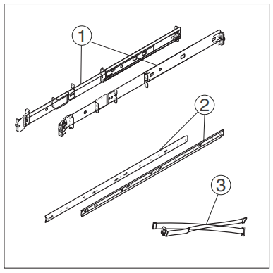 |
Locate the components for installing the rail kit assembly: |
|
|
Step 2. Install and Remove Tool-less Static Rails (Four-Post)
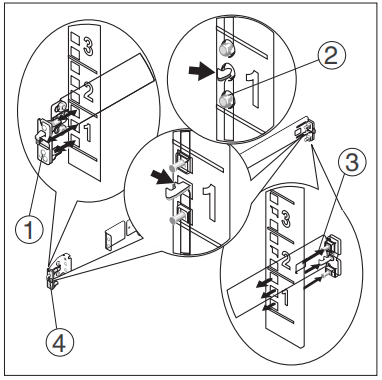 |
1. Position the left and right rail end pieces labeled FRONT facing inward and orient each end piece to seat in the holes on the front side of the vertical rack flanges. |
| 2. Align each end piece in the bottom and top holes of the first U. | |
| 3. Engage the back end of the rail until it fully seats on the vertical rack flange. Repeat these steps to position and seat the front end piece on the vertical flange. | |
| 4. To remove the rails, pull on the latch release button on the end piece midpoint and unseat each rail. |
Step 3. Configure Flush-Mount Static Rails (Two- or Four-Post)
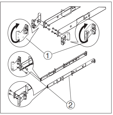 |
Note: The rails must be converted to tooled rails to install in
threaded four-post or flush-mount two-post racks.
|
| 1. Lay both rails with the end pieces facing up. Remove the two screws on the front end pieces and rotate each piece 180 degrees. | |
| 2. Reattach both end pieces with the two pairs of screws. |
Step 4. Install Flush-Mount or Center-Mount Static Rails (Two-Post)
 |
Note: To configure your rails for a tooled flush-mount
installation, refer to step 3.
|
|
| 1. Attach right and left mounting rails to the front mounting flanges with two pairs of screws. | ||
| 2. Slide each flush-mount adjustable bracket forward against the two-post rack. Secure each side to the mounting flange with two pairs of screws . | ||
| 3. For a center-mount installation: | ||
|
1) Push the back brackets toward the back of the right and left mounting rails. 2) Attach the fixed center mount brackets to the front mounting flanges with two pairs of screws. 3) Slide both of the back brackets forward against the two-post rack and secure each side to the mounting flange with two screws. |
||
Step 5. Configure Four-Post Threaded Static Rails
 |
Note: To configure your rails for a tooled installation, you
must perform step 3 and then perform the following steps for
the back brackets.
|
| 1. Press the rail release button on each rail to disengage the back brackets. | |
| 2. Rotate the back brackets 180 degrees so that the tooled end piece is in the back position. | |
| 3. With the end pieces positioned outward, align and rejoin the midsections. Slide the back brackets into place until the release button engages. |
Step 6. Install Four-Post Threaded Static Rails
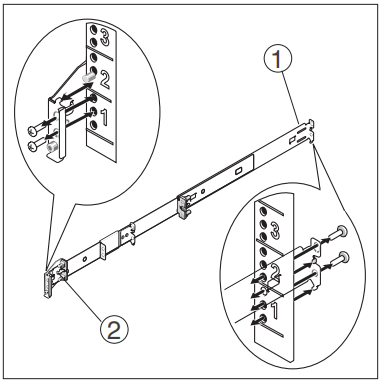 |
Note: To configure your rails for a tooled installation, refer
to step 3 and step 5.
|
| 1.Attach the right and left mounting rails to the front mounting flanges with two pairs of screws. | |
| 2.Slide the back brackets forward against the back mounting flanges and secure the brackets using two pairs of screws. |
Step 7. Install Chassis Rails
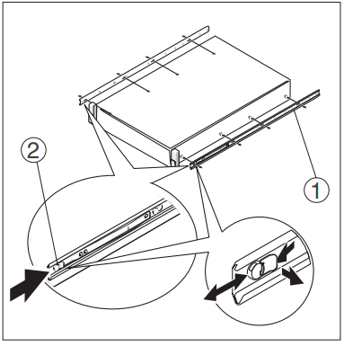 |
1.Place the system on a level surface and align the keyhole slots on the chassis rails with the pins on the system. |
| 2.Slide the chassis rails toward the back of the system until they lock into place. To remove the chassis rails, lift the lock spring until it clears the pin and slide the chassis rails toward the front of the system until the pins can slip through the keyhole slots. |
Step 8. Install the System in the Rack
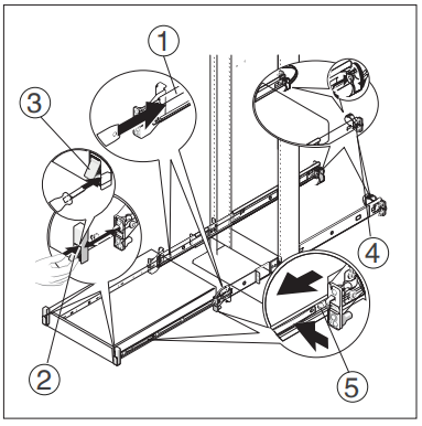 |
1.Insert the ends of the chassis rails into the front of the rails mounted to the rack and push the system into the rack. |
| 2.Depending on the rail configuration, the latches on the front of the system engage automatically. | |
| 3.If the latches do not engage automatically, secure the system in the rack by tightening the screw under each latch. | |
| 4.Thread the Velcro straps through
the slots on the back brackets and use the Velcro straps to secure the cables. |
|
| 5.To remove the system from the rack, pull the system out until the travel stops are reached. Locate the blue tabs on the sides of the chassis rails. Push the tabs inward and pull the system until the chassis rails are clear of the rails. |
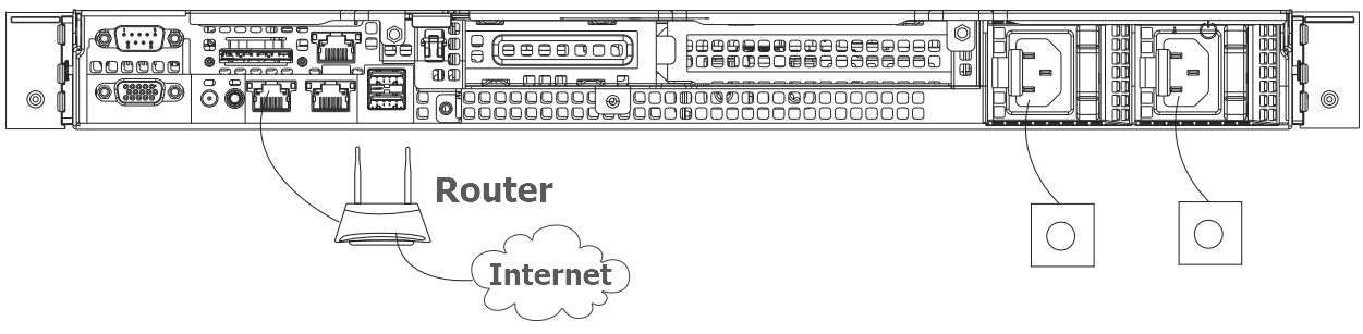
Step 9. Connect Cables
- Connect the Ethernet cable between Gb1 network port on the device and the LAN port on the switch .
- Connect a dedicated power cable to the device to power on. The power
indicator solid green after startup.